
Page 221 - Servo Motors and Industrial Control Theory -
P. 221
Appendix C 219
Adjust the gains of proportional and integral controller and the gain of velocity
feedback so that there is at least a damping ratio of 0.5 in the fundamental eigen-
values of the system matrix. You should try to increase the speed of response by
moving the eigenvalues as far away as possible from the origin of the s-plane.
Check that indeed the steady state errors are zero. Solve the state equation with
numerical integration technique, when step input of external torque is applied to
the lead screw and hence determine the maximum dynamic position error.
Select a larger motor and repeat the analysis to see if a larger motor gives a better
performance.
C.2 Electrical Stepping Servo Motors
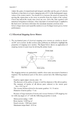
1. The mechanical parts of electrical stepping servo motors are similar to electri-
cal DC servo motors. In this section some problems are defined to highlight the
properties of stepping servo motors. The figure below shows an application of
stepping motors in open loop for driving the printer head.
Printer head
Stepping motor
Driven pulley
Gear Box Motor pulley
The stepping motors are particularly suitable when some increment of motion is
required. The mechanical parts of the above system have the following proper-
ties;
Gearbox input output velocity ratio = 30
The diameter of the pulley of motor is half the diameter of the driven pulley.
The moment of inertia of all driven parts referred to the motor gear-
box = 0.01 kg·m .
2
The viscous friction referred to the motor gearbox = 0.1 N m/rev.
Diameter of motor pulley = 5 cm
Because of large moments of inertia and viscous friction a 1 kW stepping mo-
tor with step angle of 1.8° with the following properties is used,
Motor power rating = 1 kW
Rotor inertia = 0.009 kg·m 2
Rated velocity = 3000 rpm (max)
Maximum torque limit = 20 N m