
Page 216 - Servo Motors and Industrial Control Theory -
P. 216
214 Appendix C
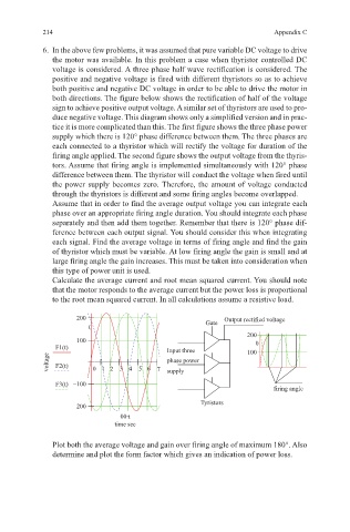
6. In the above few problems, it was assumed that pure variable DC voltage to drive
the motor was available. In this problem a case when thyristor controlled DC
voltage is considered. A three phase half wave rectification is considered. The
positive and negative voltage is fired with different thyristors so as to achieve
both positive and negative DC voltage in order to be able to drive the motor in
both directions. The figure below shows the rectification of half of the voltage
sign to achieve positive output voltage. A similar set of thyristors are used to pro-
duce negative voltage. This diagram shows only a simplified version and in prac-
tice it is more complicated than this. The first figure shows the three phase power
supply which there is 120° phase difference between them. The three phases are
each connected to a thyristor which will rectify the voltage for duration of the
firing angle applied. The second figure shows the output voltage from the thyris-
tors. Assume that firing angle is implemented simultaneously with 120° phase
difference between them. The thyristor will conduct the voltage when fired until
the power supply becomes zero. Therefore, the amount of voltage conducted
through the thyristors is different and some firing angles become overlapped.
Assume that in order to find the average output voltage you can integrate each
phase over an appropriate firing angle duration. You should integrate each phase
separately and then add them together. Remember that there is 120° phase dif-
ference between each output signal. You should consider this when integrating
each signal. Find the average voltage in terms of firing angle and find the gain
of thyristor which must be variable. At low firing angle the gain is small and at
large firing angle the gain increases. This must be taken into consideration when
this type of power unit is used.
Calculate the average current and root mean squared current. You should note
that the motor responds to the average current but the power loss is proportional
to the root mean squared current. In all calculations assume a resistive load.
2XWSXW UHFWLILHG YROWDJH
*DWH
) W ,QSXW WKUHH
YROWDJH ) W SKDVH SRZHU
VXSSO\
) W í
ILULQJ DQJOH
í 7\ULVWRUV
ÂW
WLPH VHF
Plot both the average voltage and gain over firing angle of maximum 180°. Also
determine and plot the form factor which gives an indication of power loss.