


Page 80 - Handout Digital Electronics
P. 80
Step 2: Produce the Boolean equations
From the truth table, X = 1 in the input combination, AB = 10, so this is written as:
X = AB ; Y = 1, in the input combination, AB = 01, the Boolean equation is: Y = AB , similarly Z is =1
in the input combinations AB =00 and AB =11, the Boolean equation is:
Z = AB + AB . This expression reduces to: Z = A B
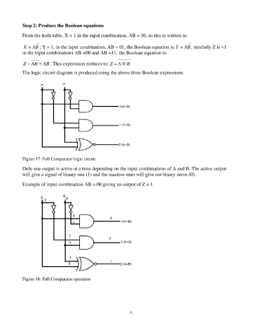
The logic circuit diagram is produced using the above three Boolean expressions.
Figure 17: Full Comparator logic circuit
Only one output is active at a time depending on the input combinations of A and B. The active output
will give a signal of binary one (1) and the inactive ones will give out binary zeros (0).
Example of input combination AB = 00 giving an output of Z = 1.
Figure 18: Full Comparator operation
80

