


Page 85 - Handout Digital Electronics
P. 85
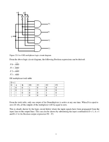
Figure 22:1 to 4 DE multiplexor logic circuit diagram

            From the above logic circuit diagram, the following Boolean expressions can be derived:

            F 0 = ABD
            F1 = ABD

            F 2 = ABD
            F 3 = ABD

            DE multiplexer truth table

             D = 1
             D    A       B       F0       F1        F2        F3
             1    0       0       1        0         0         0
             1    0       1       0        1         0         0
             1    1       0       0        0         1         0
             1    1       1       0        0         0         1


            From the truth table, only one output of the Demultiplexer is active at any one time. When D is equal to
            zero (D =0), all the outputs of the multiplexor will be equal to zero.

            This is clearly shown by the logic circuit below where the input signals have been propagated from the
            input lines to the output lines. This can also be shown by substituting the input combination D = 1, A = 1
            and B =1 in the Boolean output expression F0 – F3.


                                                                85

