Page 89 - Handout Digital Electronics
P. 89
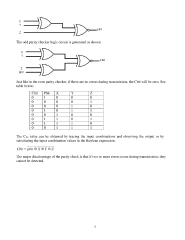
The odd parity checker logic circuit is generated as shown:


            Just like in the even parity checker, if there are no errors during transmission, the Cbit will be zero. See
            table below:

                      Cbit    Pbit    X         Y            Z
                      0       1       0         0            0
                      0       0       0         0            1
                      0       0       0         1            0
                      0       1       0         1            1
                      0       0       1         0            0
                      0       1       1         0            1
                      0       1       1         1            0
                      0       0       1         1            1

            The  Cbit  value can be  obtained by  tracing  the input  combinations  and  observing  the  output  or by
            substituting the input combination values in the Boolean expression.

            Cbit = pbit  X  Y  Z

            The major disadvantage of the parity check is that if two or more errors occur during transmission, they
            cannot be detected.


                                                                89
   84   85   86   87   88   89   90   91   92   93   94