


Page 93 - Handout Digital Electronics
P. 93
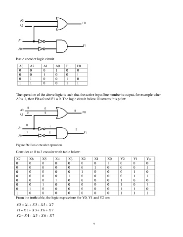
Basic encoder logic circuit

              A3     A2       A1      A0     F1      F0
              0      0        0       1      0       0
              0      0        1       0      0       1
              0      1        0       0      1       0
              1      1        0       0      1       1


            The operation of the above logic is such that the active input line number is output, for example when
            A0 = 1, then F0 = 0 and F1 = 0. The logic circuit below illustrates this point:


            Figure 26: Basic encoder operation
            Consider an 8 to 3 encoder truth table below:

            X7       X6      X5       X4       X3      X2       X1       X0       Y2      Y1       Yo
            0        0       0        0        0       0        0        1        0       0        0
            0        0       0        0        0       0        1        0        0       0        1
            0        0       0        0        0       1        0        0        0       1        0
            0        0       0        0        1       0        0        0        0       1        1
            0        0       0        1        0       0        0        0        1       0        0
            0        0       1        0        0       0        0        0        1       0        1
            0        1       0        0        0       0        0        0        1       1        0
            1        0       0        0        0       0        0        0        1       1        1
            From the truth table, the logic expressions for Y0, Y1 and Y2 are:

            YO = X1 + X 3 + X 5 + X 7
            Y1 = X 2 + X 3 + X 6 + X 7
            Y 2 = X 4 + X 5 + X 6 + X 7


                                                                93

