


Page 92 - Handout Digital Electronics
P. 92
\Address                            Chip

                   0000-00FF                             0

                   0100-01FF                             1

                   0200-02FF                             2
                   0300-03FF                             3


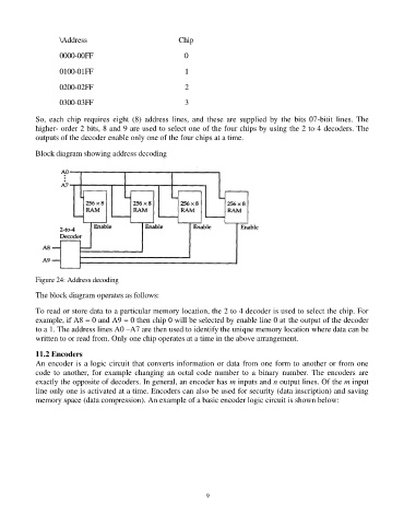
            So,  each  chip  requires  eight  (8)  address  lines,  and  these  are  supplied  by  the  bits  07-bitit  lines.  The
            higher- order 2 bits, 8 and 9 are used to select one of the four chips by using the 2 to 4 decoders. The
            outputs of the decoder enable only one of the four chips at a time.

            Block diagram showing address decoding


            Figure 24: Address decoding

            The block diagram operates as follows:

            To read or store data to a particular memory location, the 2 to 4 decoder is used to select the chip. For
            example, if A8 = 0 and A9 = 0 then chip 0 will be selected by enable line 0 at the output of the decoder
            to a 1. The address lines A0 –A7 are then used to identify the unique memory location where data can be
            written to or read from. Only one chip operates at a time in the above arrangement.

            11.2 Encoders
            An encoder is a logic circuit that converts information or data from one form to another or from one
            code  to  another,  for  example  changing  an  octal  code  number  to  a  binary  number.  The  encoders  are
            exactly the opposite of decoders. In general, an encoder has m inputs and n output lines. Of the m input
            line only one is activated at a time. Encoders can also be used for security (data inscription) and saving
            memory space (data compression). An example of a basic encoder logic circuit is shown below:


                                                                92

