


Page 87 - Handout Digital Electronics
P. 87
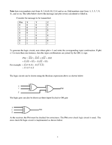
Note that even numbers start from: 0, 2,4,6,8,10,12,14 and so on. Odd numbers start from: 1, 3, 5, 7, 9,
11, and so on. The table below shows the message and pbit (even) calculated or filled in.
Consider the message to be transmitted:
Pbit X Y Z
0 0 0 0
1 0 0 1
1 0 1 0
0 0 1 1
1 1 0 0
0 1 0 1
0 1 1 0
1 1 1 1
To generate the logic circuit, note where pbit = 1 and write the corresponding input combination. If pbit
= 1 in more than one instance, then the input combinations are joined by the OR (+) sign.
Pbit = XYZ + XYZ + XYZ + XYZ
= X (YZ + YZ ) + X (YZ + YZ )
For example: = X (Y Z ) + X (Y Z )
= X Y Z
The logic circuit can be drawn using the Boolean expression above as shown below:
The logic gate can also be drawn as three-input Exclusive OR gate
At the receiver, the Pbit must be checked for correctness. The Pbit error check logic circuit is used. The
error check bit logic circuit is implemented as shown below:
87

