


Page 91 - Handout Digital Electronics
P. 91
LECTURE 11 COMBINATIONAL LOGIC CIRCUIT BUILDING BLOCKS
            11.1 Decoders
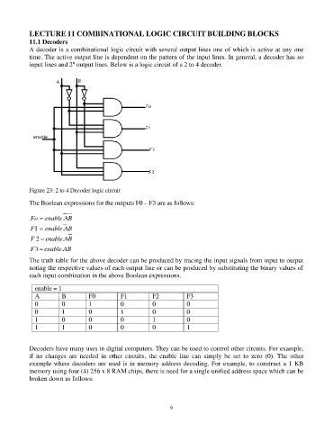
            A decoder is a combinational logic circuit with several output lines one of which is active at any one
            time. The active output line is dependent on the pattern of the input lines. In general, a decoder has no
                            n
            input lines and 2  output lines. Below is a logic circuit of a 2 to 4 decoder.


            Figure 23: 2 to 4 Decoder logic circuit

            The Boolean expressions for the outputs F0 – F3 are as follows:

            Fo = enable.AB

            F1 = enable.AB
            F 2 = enable.AB
            F 3 = enable.AB

            The truth table for the above decoder can be produced by tracing the input signals from input to output
            noting the respective values of each output line or can be produced by substituting the binary values of
            each input combination in the above Boolean expressions.

              enable = 1
              A         B         F0         F1          F2           F3
              0         0         1          0           0            0
              0         1         0          1           0            0
              1         0         0          0           1            0
              1         1         0          0           0            1


            Decoders have many uses in digital computers. They can be used to control other circuits. For example,
            if  no  changes  are  needed  in  other  circuits,  the  enable  line  can  simply  be  set  to  zero  (0).  The  other
            example where decoders are used is in memory address decoding. For example, to construct a 1 KB
            memory using four (4) 256 x 8 RAM chips, there is need for a single unified address space which can be
            broken down as follows:


                                                                91

