


Page 82 - Handout Digital Electronics
P. 82
LECTURER 10 COMBINATIONAL LOGIC CIRCUITS BUILDING BLOCKS

            10.1 Multiplexers
            A  multiplexer  (MUX)  is  a  logic  circuit  (electronic  device)  that  combines  two  or  more  inputs  into  a
            single output line. The are several types of multiplexers but in digital signal processing, a multiplexer
            selects data from several input lines, combining the data using one of the three popular techniques (
            Frequency  division  Multiplexing,  Time  Division  Multiplexing  and  Statistical  Time  Division
            Multiplexing)to a high-speed output line.


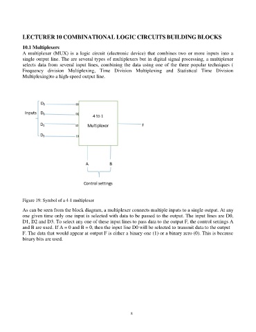
            Figure 19: Symbol of a 4-1 multiplexer

            As can be seen from the block diagram, a multiplexer connects multiple inputs to a single output. At any
            one given time only one input is selected with data to be passed to the output. The input lines are D0,
            D1, D2 and D3. To select any one of these input lines to pass data to the output F, the control settings A
            and B are used. If A = 0 and B = 0, then the input line D0 will be selected to transmit data to the output
            F. The data that would appear at output F is either a binary one (1) or a binary zero (0). This is because
            binary bits are used.


                                                                82

