


Page 83 - Handout Digital Electronics
P. 83
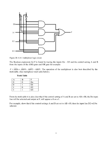
Figure 20: A 4-1 multiplexer logic circuit

            The Boolean expression for F is found by tracing the inputs Do – D3 and the control setting A and B
            from the inputs of the AND gates and OR gate for example:

            F = ABDo + ABD1 + ABD2 + ABD3 .  The  operation  of  the  multiplexer  is  also  best  described  by  the
            truth table. (See multiplexer truth table below).
                    Truth Table

                A         B        F
                0         0        Do
                0         1        D1
                1         0        D2
                1         1        D3


            From the truth table it is also clear that if the control setting of A and B are set to AB = 00, the Do input
            line will be selected and output at F, will appear a 0 or a 1.

            For example, show that if the control settings A and B are set to AB =10, then the input line D2 will be
            selected.


                                                                83

