
Page 29 - Basic PD Theory
P. 29
PD Data Types
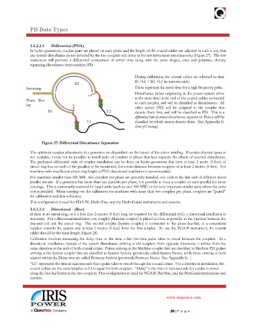
3.4.2.2.1 Differential (PDA)
In hydro-generators, coupler pairs are placed on each phase and the length of the coaxial cables are adjusted in such a way that
any system disturbance pulses detected by the two couplers will arrive at the test instrument simultaneously (Figure 27). The test
instrument will perform a differential comparison of arrival time along with the pulse shapes, sizes and polarities, thereby
separating disturbance from machine PD.
During calibration, the coaxial cables are adjusted so that:
B1+L1 = B2 +L2 (in nanoseconds)
B2
Incoming These represent the travel time for a high frequency pulse.
Disturbance pulses originating in the power system arrive
Phase Bus- at the same time at the end of the coaxial cables connected
bar to each coupler, and will be classified as disturbances. All
other pulses (PD) will be assigned to the coupler that
B1 L2 detects them first, and will be classified as PD. This is a
differential time-of-arrival disturbance separation. Pulses will be
L1 classified by which sensor detects them. (See Appendix E.
Zone of Coverage)
Figure 27: Differential Disturbance Separation
The optimum coupler placements in a generator are dependent on the layout of the stator winding. If certain physical space is
not available, it may not be possible to install pairs of couplers in places that best separate the effects of external disturbance.
The preferred differential style of coupler installation can be done on hydro-generators that have at least 1 metre (3 feet) of
circuit ring bus on each of the parallels to be monitored, for a total distance between couplers of at least 2 metres (6 feet). For
machines with insufficient circuit ring length, a PDA directional installation is recommended.
For machines smaller than 100 MW, two couplers per phase are generally installed, one each at the line end of different stator
parallel circuits. If a generator has more than two parallels per phase, it is possible to have a coupler on each parallel for more
coverage. This is customarily reserved for larger units (such as over 100 MW) or for very important smaller units where the extra
cost is justified. When carrying out the calibration for machines with more than two couplers per phase, couplers are “paired”
for calibration and data collection.
This configuration is used for PDA-IV, HydroTrac, and the HydroGuard instruments and systems.
3.4.2.2.2 Directional - (Bus)
If there is no circuit ring, or it is less than 2 metres (6 feet) long (as required for the differential style), a directional installation is
necessary. For a directional installation, one coupler (Machine coupler) is placed as close as possible to the junction between the
line-end coil and the circuit ring. The second coupler (System coupler) is connected to the phase bus-bar, at a convenient
location towards the system and at least 2 metres (6 feet) from the first coupler. To use the TGA-B instrument, the coaxial
cables should be the same length (Figure 28).
Calibration involves measuring the delay time or the time a fast rise-time pulse takes to travel between the couplers. In a
directional installation, instead of the system disturbance arriving at the couplers from opposite directions, it arrives from the
same direction at the end of both coaxial cables. Pulses arriving at the Machine coupler first are classified as Machine PD, pulses
arriving at the System coupler first are classified as System Activity (previously called System Noise), while those arriving at both
sensors within the Delay time are called Between Activity (previously Between Noise). (See Appendix E. )
“L1” represents the time in nanoseconds that a pulse takes to travel through the coaxial cables. For a directional installation, the
coaxial cables are the same lengths; so L1 is equal for both couplers. “Delay” is the time in nanoseconds for a pulse to travel
along the bus-bar between the two couplers. This configuration is used for TGA-B, BusTrac, and the BusGuard instruments and
systems.
www.irispower.com
26 | P ag e