
Page 15 - February 2021 Track N Times
P. 15
TECHNICAL TRAINING
Dust System Continued
gearbox, simply cut and replace the gearmotor ( #158920 ) which you should have in your inventory. Once gear-
motor, bearing, bearing adaptor and bearing mount are removed (both sides) you may be able to beat the auger
screw out of the auger trough with a sledge hammer. If not, you will need to replace the entire auger trough
(#158906) auger screw (#158915) auger drive shaft (#160364) auger shaft discharge end (#241831) and both bear-
ings (#160309). Someone will also need to climb inside the dust collector and clear all solidified dust from the dis-
charge funnels.
If you can keep all your rotary valves and augers running and immediately address the issue when some are not
working, the dust system becomes very easy to maintain. The longer you wait to make repairs, the more problems
you will encounter.
Now that all your augers and rotary valves are working, you
will need to inspect inside the dust collector. Remove the bot-
tom row of filters and verify you can see all 4 funnels that direct
the dust into the augers. If the collector is filled with dust you
may need to help it enter the funnels so the augers can get rid
of it. Stabbing into the funnels with a long lining bar usually
works. As mentioned before, if there is a lot of moisture in the
air the dust will be clingy and not want to move well. If you
have had no problems with augers and rotary valves, I still rec-
ommend a monthly inspection inside the dust collector, check
that all 4 funnels are clean, and air filters are not plugged. You
should also check the purge valves monthly, which is very easy
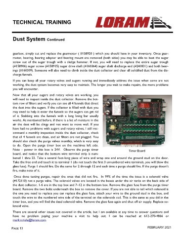
to do. Open the purge timer box on the machines left side.
Note – power in this box is 24V. Observe the purge timer Timer Board
board, and notice that the bottom wire terminal strip is num-
bered 1 thru 22. Take a several foot-long piece of wire and wrap one end around the ground stud on the door.
Take the free end and touch it to terminal 1 (do not touch the first 3 unnumbered wire terminals, you will blow the
glass fuse). Purge 1 should fire. Do the same for 2 through 12 and each time a purge should fire. If the purge doesn’t
fire, make note of it.
Once done testing purges, repair the ones that did not fire. In 99% of the time the issue is a solenoid valve
(#172110) not a purge valve. The solenoid valves are located in the boxes under the air tanks on the back side of
the dust collector, 1-6 are in the top box and 7–12 in the bottom box. Remove the glass fuse from the purge timer
board. Remove the two bolts underneath the box to remove the cover. If you are not able to tell which solenoid is
the one you need to replace you can replace the glass fuse, attach your wire to the ground stud in the box, and
touch the wire to the numbered wire side of the terminal on the solenoids coil. This is the same as you did in the
timer box, and you will find the dead solenoid valve. Remove the glass fuse again and shut off air supply. Replace so-
lenoid valve.
There are several other issues not covered in the article, but I am available at any time to answer questions and
have no problem paying your machine a visit to help out. I can be reached at 612-270-4866 or
mark.v.riola@loram.com.
Page 13 FEBRUARY 2021