
Page 25 - Апрель
P. 25
METALWORKING EQUIPMENT AND TOOLS
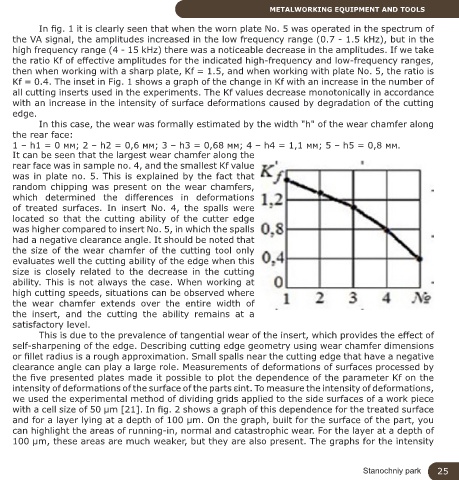
In fig. 1 it is clearly seen that when the worn plate No. 5 was operated in the spectrum of
the VA signal, the amplitudes increased in the low frequency range (0.7 - 1.5 kHz), but in the
high frequency range (4 - 15 kHz) there was a noticeable decrease in the amplitudes. If we take
the ratio Kf of effective amplitudes for the indicated high-frequency and low-frequency ranges,
then when working with a sharp plate, Kf = 1.5, and when working with plate No. 5, the ratio is
Kf = 0.4. The inset in Fig. 1 shows a graph of the change in Kf with an increase in the number of
all cutting inserts used in the experiments. The Kf values decrease monotonically in accordance
with an increase in the intensity of surface deformations caused by degradation of the cutting
edge.
In this case, the wear was formally estimated by the width "h" of the wear chamfer along
the rear face:
1 – h1 = 0 мм; 2 – h2 = 0,6 мм; 3 – h3 = 0,68 мм; 4 – h4 = 1,1 мм; 5 – h5 = 0,8 мм.
It can be seen that the largest wear chamfer along the
rear face was in sample no. 4, and the smallest Kf value
was in plate no. 5. This is explained by the fact that
random chipping was present on the wear chamfers,
which determined the differences in deformations
of treated surfaces. In insert No. 4, the spalls were
located so that the cutting ability of the cutter edge
was higher compared to insert No. 5, in which the spalls
had a negative clearance angle. It should be noted that
the size of the wear chamfer of the cutting tool only
evaluates well the cutting ability of the edge when this
size is closely related to the decrease in the cutting
ability. This is not always the case. When working at
high cutting speeds, situations can be observed where
the wear chamfer extends over the entire width of
the insert, and the cutting the ability remains at a
satisfactory level.
This is due to the prevalence of tangential wear of the insert, which provides the effect of
self-sharpening of the edge. Describing cutting edge geometry using wear chamfer dimensions
or fillet radius is a rough approximation. Small spalls near the cutting edge that have a negative
clearance angle can play a large role. Measurements of deformations of surfaces processed by
the five presented plates made it possible to plot the dependence of the parameter Kf on the
intensity of deformations of the surface of the parts εint. To measure the intensity of deformations,
we used the experimental method of dividing grids applied to the side surfaces of a work piece
with a cell size of 50 μm [21]. In fig. 2 shows a graph of this dependence for the treated surface
and for a layer lying at a depth of 100 μm. On the graph, built for the surface of the part, you
can highlight the areas of running-in, normal and catastrophic wear. For the layer at a depth of
100 μm, these areas are much weaker, but they are also present. The graphs for the intensity
Stanochniy park 25