
Page 15 - StanochnyPark
P. 15
METALWORKING EQUIPMENT METALWORKING EQUIPMENT
AND TOOLS AND TOOLS
PRECISION OF GEAR HOBBING form a kinematic connection between the tool and the work piece reaches 15 with the same
number of kinematic chain shafts. The emergence of high-frequency components is caused by
MACHINES WITH DIRECT ROTATION the superposition of errors in the intermediate gears of the kinematic chain of the machine and
the frequency of their manifestation per revolution of the pitch wheel. Their value depends on
This article discusses the main OF TOOL AND WORKPIECE the gear ratio between the given gear and the final link.
features of the formation of the
kinematic errors of new generation
gear hobbing machines with direct drives of rotation of the cutter and workpiece. On the
experimental machine 5320F4 of class P accuracy, an accuracy was obtained that is five times
higher than the accuracy according to GOST 659-89. The directions in the design and production
of these machines are determined, excluding the use of special technologies in contrast to
traditional machines.
The peculiarity of the developments of modern
CNC machines is the modular design principle based on Table rotation error (product
mechatronic modules. In this case, traditional kinematic
chains in machine tools are partially or completely
replaced by mechatronic devices, which, as a rule, are
functionally compatible with the executive bodies of the spindle) 1 revolution of the table (product spindle)
machine. Gear hobbing machines are no exception [2].
When developing machine tools of a new generation,
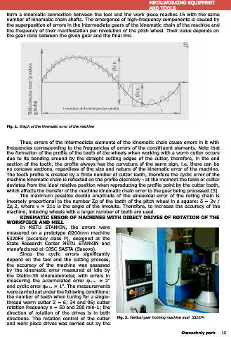
most companies use direct drives to rotate the cutter Fig. 1. Graph of the kinematic error of the machine.
and the work piece, as a result of which the sources
of motion are located directly on the working body of
the machine, while there are no intermediate gears between it and the final link. Consequently, Thus, errors of the intermediate elements of the kinematic chain cause errors in it with
clearances in gears are eliminated, high rigidity is provided when transferring rotation from the frequencies corresponding to the frequencies of errors of the constituent elements. Note that
engine to the tool and work piece. the formation of the profile of the teeth of the wheels when working with a worm cutter occurs
This solution makes it possible not to use precise gears, which have a decisive effect due to its bending around by the straight cutting edges of the cutter, therefore, in the end
on the kinematic accuracy of the machine, which with direct drives is determined mainly by section of the tooth, the profile always has the curvature of the same sign, i.e. there can be
feedback sensors and the dynamic characteristics of the drives and changes little (due to the no concave sections, regardless of the size and nature of the kinematic error of the machine.
absence of wear) during operation. In addition, a number of advantages appear: simplification The tooth profile is created by a finite number of cutter teeth, therefore the cyclic error of the
of the design of the machine as a result of a decrease in the number of original parts by about machine kinematic chain is reflected on the profile discretely - at the moment the table or cutter
5 - 7 times; no restrictions on increasing the cutting speed, which provides the possibility of deviates from the ideal relative position when reproducing the profile point by the cutter tooth,
using carbide tools and obtaining various modifications of the tooth in length, and also allows which affects the transfer of the machine kinematic chain error to the gear being processed [3].
you to process gear wheels of high hardness. The maximum possible double amplitude of the sinusoidal error of the rolling chain is
PRECISION OF GEAR WHEELS AND MACHINES inversely proportional to the number Zд of the teeth of the pitch wheel in a square: δ = 2ν /
For each degree of accuracy of gears according to GOST 1643-81, the following indicators Zд 2, where ν ≈ 21о is the angle of the involute. Therefore, to increase the accuracy of the
are established: kinematic accuracy, smoothness of operation, tooth contact. Many performance machine, indexing wheels with a larger number of teeth are used.
characteristics depend on the accuracy of the gears, including permissible peripheral speed and KINEMATIC ERROR OF MACHINES WITH DIRECT DRIVES OF ROTATION OF THE
durability. So, in turbine wheels, with a degree of accuracy of 4 - 3 - 4, a peripheral speed of WORKPIECE AND MILL
130 m / s and more is achieved. In MSTU STANKIN, the errors were
Kinematic errors of hobbing machines equipped with hob cutters affect the first two measured on a prototype Ø200mm machine
indicators of the accuracy of gear wheels, in particular, the accumulated error of the circumferential 5320F4 (accuracy class P), designed at the
pitch of the wheel is approximately 90 % dependent on the error of the machine, while the error State Research Center MSTU STANKIN and
in the direction of the tooth depends on the error of the machine by 50 %, and the error the manufactured at OJSC SASTA (Sasovo).
profile of the teeth - by 25 % [3]. Since the cyclic errors significantly
The kinematic error of the machine is determined by the deviation from the theoretical depend on the tool and the cutting process,
gear ratio between the tool and the work piece at each point in time. The accuracy of the the accuracy of the machine was assessed
kinematic chain of the interconnected position of the table (product spindle) relative to the by the kinematic error measured at idle by
tool spindle is characterized by: the accumulated error φк.н. rotation and periodic (cyclic) error the Diakin-3R kinematometer, with errors in
φк.ц. (fig. 1). The reasons for the occurrence of kinematic error in machines with a mechanical measuring the accumulated error φк.н. ≈ 2"
connection between the cutter and the work piece (traditional machines) and errors in machines and cyclic error φк.ц. ≈ 1". The measurements
with direct drives of rotation of the cutter and table have fundamental differences. were carried out under the following conditions:
KINEMATIC ERROR IN TRADITIONAL MACHINES the number of teeth when tuning for a single-
Low-frequency component of kinematic error, which is error φк.н. due primarily to thread worm cutter Z = 6; 24 and 96; cutter
manufacturing and installation errors dividing worm wheel of the table spindle, which are made rotation frequency n = 50 and 200 min-1; the
up of the accumulated error of the circumferential step, radial and end beats [3, 4]. direction of rotation of the drives is in both
High-frequency component, error φк.ц. caused by the presence of errors in the intermediate directions. The rotation control of the cutter Fig. 2. Vertical gear hobbing machine mod. 5320F4.
gears of the kinematic chain. In medium-sized machines, the number of pairs of gears that and work piece drives was carried out by the
14 Stanochniy park Stanochniy park 15