Page 20 - StanochnyPark
P. 20

METALWORKING EQUIPMENT                                                                                                                                                                               METALWORKING EQUIPMENT
         AND TOOLS                                                                                                                                                                                            AND TOOLS
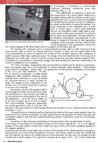
                                                                  a  microscope,  a  computer,  a  short-length                  surface, the normal load of a steel ball with a diameter of Dшар = 30 mm is 0.25 N;
                                                                  reference  standard,  connecting  wires and                    ● circular speed of rotation of the shaft nвал [rpm];
                                                                  software (Fig. 1 - 3).                                         ● the circular speed of rotation of the ball nшар [rpm], determined from the relationship nшар
                                                                         The  tribotester  is designed  to  pose  the            = nвал × dвал / Dшар 1, where dвал is the diameter of the shaft at the points of contact with the
                                                                  ball and rotate it at a given speed relative to a              ball, Dшар 1 is the diameter of the ball section at the points of contact with the shaft;
                                                                  specified sample with (or without) coating for a
                                                                  specified test time, as well as for the possibility            Table 1. Results of measurements and calculations of testing the substrate.
                                                                  of reinstalling the sample in order to replace it
                                                                  or obtain a new print on a specified surface. The                      measurements                                               calculation
                                                                                                                                                                                x
                                                                                                                                                                                                                                    x
                                                                                                                                                                                                                   -5
                                                                                                                                                                                                                                               3
                                                                                                                                                                                                                                        5
                                                                                                                                                                                                               x
                                                                                                                                                                                    5
                                                                                                                                                                                                  x
                                                                                                                                                                                                      -13
                                                                  main  elements  of  the  tribotester  are:  a  base              № bipar, μm biperp, μm          b, μm     Vs 10 , μm   3    Кs 10 ,        Is 10 , mm/m       Ws 10 , μm /s
                                                                                                                                                                                                    -
                                                                                                                                                                                                        -
                                                                  with a  control panel,  a  drive  shaft  fastening                                                                          m N 1m 1
                                                                                                                                                                                                 3
                                                                  device, an adjustable object table with a vice,                   1     654,15       654,15      681,9         7,07             8,96            22,41                0,24
                                                                  a DC motor, a frequency converter, a counter-
                                                                  timer, and control elements. The test specimen                    2     699,59       699,15
                                                                  is installed motionlessly perpendicular  to the                   3     692,01       692,01
                                                                  plane of rotation of the ball on the supporting
        Fig. 2. View of the tribotester after installing the ball.  surfaces of the vise jaws. On the control panel              ● test time tисп. [c] (taken on the basis of test tests or knowledge of specific coating properties);
                                                                  of  the  tribotester, two parameters,  which are               ● the length of the sliding path of the ball relative to the plane of the sample S = tисп. × nшар
        the rotation speed of the drive shaft and the duration of the tests, are set.                                            π•Dшар, where tисп. - test time [min], nшар - ball circular speed [rpm], Dшар - ball diameter [mm].
               To  visualize  the  abrasion  zone,  a  monovideomicroscope  with  a  high-resolution  zoom                       The main measured parameters on the print are: bpar, bperp, apar, aperp (Fig. 4).
        lens  is  used,  with  a  holder  for  coarse  and  fine  focusing,  a  base,  and  an  object  table  with                     The main design parameters for microabrasive wear tests are:
        micro-movements. In order to transfer the image of the research object to the computer, a                                ● for samples of the base material (substrate) without coatings (samples with a coating with an
        digital eyepiece USB video camera is used. The image is transmitted from the microscope to a                             indentation depth less than the coating thickness): volumetric wear of the substrate
        computer via a USB cable, where it can be viewed, measured, and also saved as graphic files.
        A program for visualizing a microscopic image and determining the geometric dimensions of                                                              ,
        prints is installed on the computer.                                                                                     or bulky wear of the coating when the indent depth is less than the coating thickness
               The main (variable, replaceable) test components are balls and an abrasive suspension.
        Balls  are  mainly  used  from  the  production  of  rolling  bearings.  Balls  material  -  heat-treated
        steel  ShKh15,  hardness  -  60-62  HRC.  The  parameter  of  the  surface  roughness  of  the  balls                    where R is the radius of the ball used, b is the average diameter of the substrate indentation
        is  Ra  =  0.1  μm.  Ball  diameter  -  30  mm.
        As  an  abrasive  suspension,  a  water-based                      sample                           ball                 bipar and biperp

                                                                                                                                        b = (bipar ср + biperp ср)/2;
        suspension  with synthetic  diamond  single
        crystals with a diameter of 1 μm (or based                                                                               ● for coated samples (indentation depth is greater than the coating thickness): volumetric wear
        on electrocorundum) is used.  During  the                                                                                of the coating
        tests,  the  supply  of  the  suspension  to  the
        friction zone is strictly dosed and repeated                                                                                                          [мм3],
        in a given time interval.
               For measurements, flat samples with a                                                                             Table 2. Calculation results of MultiPateks coating test on P6M5 steel for average indentation
        coating applied to the end surface are used.                                                                             diameters a = 585 μm and b = 639 μm.
        The dimensions of the samples are limited                                                                                   Vs 10 5   Vc 10 5    (Vs+Vc)     Kc 10 -13  Ic 10 -5  Wc 10 5  Ks 10 -13  Is10 -5  Ws 10 5   Ics 10 -5  Wcs 10 5
                                                                                                                                                                                                                        x
                                                                                                                                                                                                                                   x
                                                                                                                                                                                                                                              x
                                                                                                                                                x
                                                                                                                                     x
                                                                                                                                                                                                     x
                                                                                                                                                                                x
                                                                                                                                                                                           x
                                                                                                                                                                      x
        by the dimensions of the jaws of the vice of                                                               drive                                  X 10 5
                                                                                                                   shaft
        the tribotester - up to 30 mm in width, up
        to 40 mm in length, up to 10 mm in height.                Fig. 3. Layout of the sample relative to the ball and drive       μm  3      μm 3       μm  3     m N m -1  mm /m      μm /s     m N m -1  mm /m     μm /s     mm /m      μm /s
                                                                  shaft
                                                                                                                                                                                                    3
                                                                                                                                                                                                      -1
                                                                                                                                                                                                               3
                                                                                                                                                                                 3
                                                                                                                                                                     3
                                                                                                                                                                                                                         3
                                                                                                                                                                                                                                               3
                                                                                                                                                                       -1
                                                                                                                                                                                            3
                                                                                                                                                                                                                                    3
        The  recommended  roughness  parameter
        for coated specimens is Ra ≤ 0.32 µm. The
        flatness of the end surfaces of the sample should not exceed 0.05 µm. Recommended coating                                    3,8       1,6         5,5        6,9       5,2       0,05       4,9      12,2     0,13       17,3       0,18
        thickness > 1 µm.
               The test duration is determined by obtaining the depth of the wear crater greater than the
        thickness of the coating. Evaluation of wear parameters is also possible for thick coatings (the                         Table 3. Calculation results of the TiN coating test on R6M5 steel for medium diameters of
        indentation depth is less than the coating thickness) and for a monolithic material, for example,                        prints, a = 585 μm and b = 639 μm.
        a substrate.                                                                                                                Vs 10 5    Vc 10 5    (Vs+Vc)    Kc 10 -13  Ic 10 -5  Wc 10 5   Ks 10 -13  Is10 -5  Ws 10 5    Ics 10 -5  Wcs 10 5
                                                                                                                                                                                                                                    x
                                                                                                                                                                                                                          x
                                                                                                                                                                                                      x
                                                                                                                                                                                                                                                x
                                                                                                                                                                       x
                                                                                                                                                                                 x
                                                                                                                                      x
                                                                                                                                                 x
                                                                                                                                                                                            x
               Constancy of the following parameters is fundamental to the reproducibility of tests:                                                       X 10 5
        ● the angle of inclination of the sample surface to the horizon (about 60 - 75 °), the optimal
        position of the ball relative to the drive shaft (the axis of the drive shaft should be parallel to                          μm 3       μm 3       μm 3      m N m -1  mm /m      μm /s     m N m -1  mm /m     μm /s     mm /m       μm /s
                                                                                                                                                                                                                                                 3
                                                                                                                                                                                                                                     3
                                                                                                                                                                                                                           3
                                                                                                                                                                                                                 3
                                                                                                                                                                      3 -1
                                                                                                                                                                                  3
                                                                                                                                                                                                     3 -1
                                                                                                                                                                                             3
        the sample surface);
        ● normal load of a free-lying ball to the surface of the sample N [H], determined by calculation,                                       9,81       12,01       7,61     15,54      0,16       1,39     3,49      0,04      19,03       0,2
        depending on the mass of the specifically used ball, its location relative to the drive shaft and                            2,2
        the test sample, as well as the coefficients of friction between the ball with the sample surface
        and the drive shaft surface. For a specimen located at an angle of 60 - 75 ° to the horizontal
      20   Stanochniy park                                                                                                                                                                                                     Stanochniy park       21
   15   16   17   18   19   20   21   22   23   24   25