
Page 82 - QR CIMAR LASER SCREED
P. 82
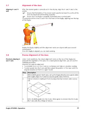
3.7 Alignment of the Axes
Aligning X- and Y- After the desired grade is correctly set in the display, align the X- and Y-axis to the
axis
jobsite.
Ensure that the bubble of the circular level is positioned near the centre of the
circle for maximum self-levelling capability.
Ensure that the Rugby is properly positioned over a control point.
The direction of the X-Axis is seen from the front of the Rugby, sighting over the top
of the Rugby.
007827_001
Rotate the Rugby slightly until the alignment marks are aligned with your second
control point.
Once the Rugby is aligned, you can start working.
3.8 Precise Alignment of the Axes
Precisely aligning X- Under most conditions, the raised alignment marks on the top of the Rugby are
and Y-axis adequate for alignment of the axes. For a more precise alignment, you can use the
following procedure.
Objective of a precise alignment:
• To establish Point A on the Y-axis as a reference and take an elevation reading.
• To enter grade into the X-axis and then adjust the position of the laser until the
original elevation at Point A is again found.
Step Description
1.
With 0.000% grade in both axes, set up the Rugby directly over a grade stake
2. and roughly align the Y-axis to a second grade stake (Point A).
Take an elevation reading at Point A using a Rod Eye receiver and a survey
rod.
3. Enter +5.000% grade into the X-axis. When grade is entered into the X-axis,
the Y-axis acts like a hinge or fulcrum.
Rugby 870/880, Operation 22