
Page 51 - SSAB Welding Handbook Edition 2
P. 51
©2009-2019 by SSAB Group of companies (SSAB). All rights reserved. Only digital PDF file. No distribution. No printing allowed!
No part of this handbook may be reproduced in any form or by any means without permission in writing from SSAB.
Welding handbook 8.0 Fatique in welded joints
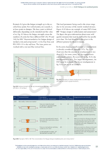
Formula 8.2 gives the fatigue strength up to the so- The load parameter being used is the stress range
called knee point. For welded joints, m is usually 3, due to the presence of the tensile residual stresses.
©SSAB
at knee point m changes. The knee point is defined Figure 8.10 shows an example of some FAT’s from
differently depending on the standard and the value IIW “Fatigue design of welded joints and components”.
of m. Fig. 8.9 shows the fatigue strength versus the The figure also gives information about some weld
numbers of cycles for three different FAT (56, 90 and quality demands that must be fulfilled for the specific
140) for IIW “Recommendation for fatigue design of joint class. The load direction is also given in the
welded joints and components”, in the blue lines and different pictures for the joint classes.
EN 1993-1-9 in the red lines. The knee points are
marked with a red and blue vertical line. In the joint classes, a small amount of misalignment
is already considered, typically 15%. Fig. 8.10
illustrates that the amount of misalignment is less
than 15% for some joints, see the requirements
1000 and remark column. For joint 213 in fig. 8.10, the
misalignment is 10%. For larger misalignment, the
FAT must be reduced. The linear misalignment in
Stress range/MPa 100
fig. 8.11 can act as an example.
e t
10
1.0E+04 1.0E+05 1.0E+06 1.0E+07 1.0E+08 1.0E+09
Number of cycles Fig. 8.11: Example of a linear misalignment. e is the linear
misalignment and t is plate thickness.
Fig. 8.9: Fatigue strength for IIW recommendation, blue lines, and
EN 1993-1-9, red lines.
No. Structural detail Description FAT FAT Requrirements and remarks
(St. = steel; Al. = Aluminium) St. [MPa] Al. [MPa]
200 Butt welds, transverse loaded
Transverse loaded butt weld 112 45 All welds ground flush to surface, grinding
211 (X-groove or V-groove) ground parallel to direction of stress. Weld run-on
Force flush to plate, 100% NDT and run-off to be used and subsequently
removed. Plate edges to be ground flush in
direction of stress. Welded from both sides.
Force
Force
Misanlignment <5% of plate thickness.
Required quality cannot be inspected by
NDT!
212 Transverse butt weld mad in shop in 50 36 Weld run-on and run-off piece to be used
flat position NDT weld reinforcement and subsequently removed. Plate edges
<0.1 thickness to be ground flush in direction of stress.
Welded from both sides. Milalignment <5%
of plate thickness.
213 Transverse butt weld not satisfying 80 Weld run-on and run-off pieces to be used
conditions of 212, NDT and subsequently removed. Plate edges
to be ground flush in direction of stress.
Al.: Butt weld with toe angle < 50° 32 Welded from both sides. Misalignment <10%
Butt weld with toe angle > 50° 25 of plate thickness.
Fig. 8.10: Example of FAT in IIW “Recommendation for fatigue design of welded joints and components”.
This handbook contains general suggestions and information without any expressed or implied warranty of any kind. SSAB hereby expressly disclaims
all liability of any kind, including any damages, in connection with the use of the information and for their suitability for individual applications. 51
It is the responsibility of the user of this brochure to adapt the recommendations contained therein to the requirements of individual applications.