
Page 452 - Kitab3DsMax
P. 452
Part III: Modeling Basics
Using the Symmetry tools
The Polygon Modeling panel also holds a link for accessing the Symmetry tools. This command opens the
Symmetry Tools dialog box, shown in Figure 14.6. Using this dialog box, you can select an object with the
top button and automatically copy the changes on either side of any axis to the opposite side with the + to −
and − to + buttons. You also can use the Flip Symmetry button to switch the moved subobjects to the oppo-
site side of the model.
The Copy Selected button lets you copy the position of an entire object or of just the selected vertices and
paste them onto another object with the same number of vertices.
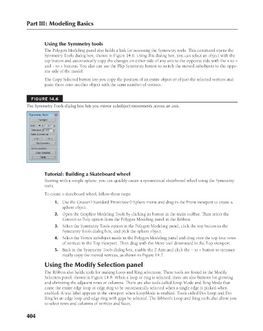
FIGURE 14.6
The Symmetry Tools dialog box lets you mirror subobject movements across an axis.
Tutorial: Building a Skateboard wheel
Starting with a simple sphere, you can quickly create a symmetrical skateboard wheel using the Symmetry
tools.
To create a skateboard wheel, follow these steps:
1. Use the Create ➪ Standard Primitives ➪ Sphere menu and drag in the Front viewport to create a
sphere object.
2. Open the Graphite Modeling Tools by clicking its button in the main toolbar. Then select the
Convert to Poly option from the Polygon Modeling panel in the Ribbon.
3. Select the Symmetry Tools option in the Polygon Modeling panel, click the top button in the
Symmetry Tools dialog box, and pick the sphere object.
4. Select the Vertex subobject mode in the Polygon Modeling panel and drag over the top four rows
of vertices in the Top viewport. Then drag with the Move tool downward in the Top viewport.
5. Back in the Symmetry Tools dialog box, enable the Z Axis and click the − to + button to symmet-
rically copy the moved vertices, as shown in Figure 14.7.
Using the Modify Selection panel
The Ribbon also holds tools for making Loop and Ring selections. These tools are found in the Modify
Selection panel, shown in Figure 14.8. When a loop or ring is selected, there are also buttons for growing
and shrinking the adjacent rows or columns. There are also tools called Loop Mode and Ring Mode that
cause the entire edge loop or edge ring to be automatically selected when a single edge is picked when
enabled. A text label appears in the viewport when LoopMode is enabled. Tools called Dot Loop and Dot
Ring let an edge loop and edge ring with gaps be selected. The Ribbon’s Loop and Ring tools also allow you
to select rows and columns of vertices and faces.
404
6/30/10 4:23 PM
21_617779-ch14.indd 404 6/30/10 4:23 PM
21_617779-ch14.indd 404