Page 770 - Kitab3DsMax
P. 770
Part VI: Advanced Modeling
                                             You can also use the Bevel Deformation window to select three different types of beveling: Normal,
                                             Adaptive Linear, and Adaptive Cubic. Table 27.3 shows and describes the buttons for these three beveling
                                             types. You can select them from a flyout at the right end of the window.
                                        TABLE 27.3
                                       Toolbar Button  Name       Bevel Deformation Buttons
                                                                       Description
                                                       Normal Bevel    Produces a normal bevel with parallel edges, regardless of the path angle
                                                       Adaptive (Linear)  Alters the bevel linearly, based on the path angle
                                                       Adaptive (Cubic)  Alters the bevel using a cubic spline, based on the path angle


                                             Fit Deformation
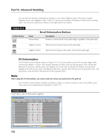
                                             The Fit Deformation window, shown in Figure 27.21, lets you specify a profile for the outer edges of the
                                             cross-section shapes to follow. This window includes two lines: one red and one green. The red line dis-
                                             plays the X-axis scale, and the green line displays the Y-axis scale. By default, both lines are positioned
                                             equally at the 100 percent value. Specifying a value that is greater than 100 percent increases the scale, and
                                             specifying a value less than 100 percent has the opposite effect.

                                      Note
                                      When using the Fit deformation, you cannot make the surface go backward on the path. n
                                             The Fit Deformation window includes ten buttons unique to it that are used to control the profile curves.
                                             These buttons are illustrated and described in Table 27.4.


                                        FIGURE 27.21
                                      A Loft object with Fit Deformation applied


                                      722

