
Page 175 - Foton Workshop Manual - Auman EST-M
P. 175
Diagnosis - Diagnosis-fault diagnosis of electronic and electrical parts DI - 121
3. Check the communication line between the ABSECU and the diagnostic interface IN
a. Ignition switch:LOCK.
b. Disconnect the cable of battery negative pole DI
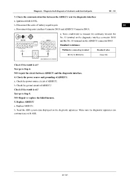
c. Disconnect diagnosis interface Connector B018 and ABSECU Connector B018.
d. Take a multimeter to measure the continuity between the EG
No. 15 terminal on the diagnostic interface connector B018
and the No. 10 terminal on the ABSECU connector B063. TR
Standard resistance:
Multimeter connecting terminal Standard value AX
B018(15)-B063(10) About 0Ω
FR
Check if the result is ok? ST
Yes>go to Step 4.
NO>repair the circuit between ABSECU and the diagnostic interface. BR
4. Check the power source and grounding of ABSECU.
a. Check the power source circuit of ABSECU. BW
b. Check the ground circuit of ABSECU.
Check if the result is ok? EL
Yes>go to Step 5.
NO>Repair or replace the failed harness.
5. Replace ABSECU
a. Replace ABSECU.
b. Read the ABS system data displayed on the diagnostic apparatus. Make sure the diagnostic apparatus can
communicate with ABS.
DI-121