
Page 1276 - Workshop Manual - Aumark (BJ1051)
P. 1276
61-4
Circuit-Guide to circuit
System summarization-⑩
· Battery provides current, and current is supplied to the controller of central control lock through fuse F/L 0 inside of
chassis fuse box, fuse F/L 2 and fuse F13 inside of body fuse box, controlling the door opening and locking.
· Left door lock will be locked when the driver presses down the button of left door lock. Pin No. 6 of central
control lock controller to pin No. 1 of left front door lock, and ground through pin No. 2 of left front door lock
passing the switch of left door to produce the grounding signal. The grounding signal input to central control
lock controller will be used to confirm the left door is under locked. Current goes to pin No. 1 of right front door
lock through pin No. 4 of central control lock controller, then goes to motor, pin No. 2 of right front door lock,
to pin No. 2 of central control lock controller; the motor gets electrified and runs to forward direction, and the
right front door is locked.
· Left door lock will be opened when the driver lifts the left door lock button. The pin No. 6 of central control
lock controller can not form a return circuit, so there will be no grounding signal generated. There is no
grounding signal input into central control lock controller, so it is confirmed that the left door is open. Current
goes to pin No. 2 of right front door lock through pin No. 2 of central control lock controller, then goes to
motor, pin No. 1 of right front door lock, to pin No. 4 of central control lock controller; the motor gets
electrified and runs to reverse direction, and the right front door is opened.
Service hint-11
· B035 controller of central control lock
3- grounding: voltage is about 24V.
4- grounding: moment voltage is about 24V when the button of left door lock is pressed.
2- grounding: moment voltage is about 24V when the button of left door lock is lifted.
· D005 right front door lock
1- grounding: moment voltage is about 24V when the button of left door lock is pressed.
2- grounding: moment voltage is about 24V when the button of left door lock is lifted.
· E005 left front door lock
1-2: resistance is about 0 when the button of left door lock is pressed down and the contact point is closed.
Resistance is about∞when the button of left door lock is lifted and the contact point is opened.
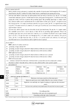
口: part position-12
Reference wire Reference wire Reference wire
S/N S/N S/N
harness harness harness
B035 Body wire C051 Chassis wire E005 Left door wire
B050 Body wire D005 Right door wire
61 : insert parts among wire harnesses-13
S/N S/N Reference wire harness (position of the insert parts)
B103 C101 Body wire and chassis wire (middle of the first cross member of frame)
Right door wire and body wire (right of washing pot right under the instrument
D101 B101
panel)
E101 B111 Left door wire and body wire(clutch pedal left under the instrument panel)
: grounding-14
S/N Grounding position
B206 Grounding on the right side of instrument panel
B207 Grounding on the right side of front panel
* It is just an example and it is different from actual system circuit description.
Page 1276