
Page 217 - Workshop Manual - Aumark (BJ1051)
P. 217
04-73
Diagnosis-ABS system
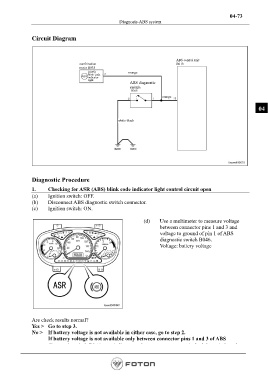
Circuit Diagram
ABS control unit
combination B013
meter B033
(ABS) orange
blink code
indicator
light.
ABS diagnostic
switch
orange
04
white-black
Diagnostic Procedure
1. Checking for ASR (ABS) blink code indicator light control circuit open
(a) Ignition switch: OFF.
(b) Disconnect ABS diagnostic switch connector.
(c) Ignition switch: ON.
(d) Use a multimeter to measure voltage
between connector pins 1 and 3 and
voltage to ground of pin 1 of ABS
diagnostic switch B046.
Voltage: battery voltage
Are check results normal?
Yes > Go to step 3.
No > If battery voltage is not available in either case, go to step 2.
If battery voltage is not available only between connector pins 1 and 3 of ABS
diagnostic switch B046, repair line open between connector pin 3 of the switch and
ground.
Page 217