
Page 19 - GP Fall 2019
P. 19
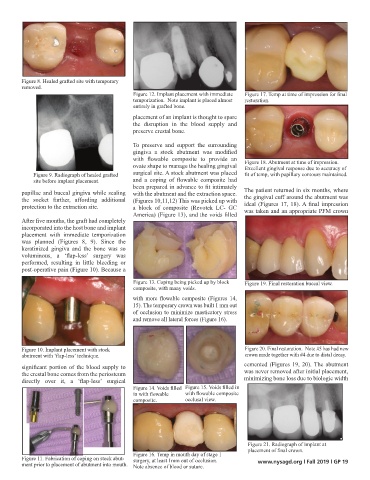
Figure 8. Healed grafted site with temporary
        removed.
                                             Figure 12. Implant placement with immediate   Figure 17. Temp at time of impression for final
                                             temporization.  Note implant is placed almost   restoration.
                                             entirely in grafted bone.
                                             placement of an implant is thought to spare
                                             the disruption in the blood supply and
                                             preserve crestal bone.

                                             To preserve and support the  surrounding
                                             gingiva  a  stock  abutment  was  modified
                                             with  flowable  composite  to  provide  an   Figure 18. Abutment at time of impression.
                                             ovate shape to manage the healing gingival   Excellent gingival response due to accuracy of
            Figure 9. Radiograph of healed grafted   surgical site. A stock abutment was placed   fit of temp, with papillary contours maintained.
            site before implant placement.   and  a  coping  of  flowable  composite  had
                                             been prepared in advance to fit intimately
        papillae and buccal gingiva while sealing  with the abutment and the extraction space.   The patient returned in six months, where
        the  socket  further, affording additional  (Figures 10,11,12) This was picked up with   the gingival cuff around the abutment was
        protection to the extraction site.   a  block  of composite  (Revotek  LC-  GC   ideal (Figures 17, 18). A final impression
                                             America) (Figure 13), and the voids filled   was taken and an appropriate PFM crown
        After five months, the graft had completely
        incorporated into the host bone and implant
        placement  with immediate  temporization
        was planned (Figures 8, 9). Since the
        keratinized  gingiva  and the  bone was so
        voluminous,  a  ‘flap-less’  surgery  was
        performed,  resulting  in  little  bleeding  or
        post-operative pain (Figure 10). Because a
                                             Figure 13. Coping being picked up by block   Figure 19. Final restoration buccal view.
                                             composite, with many voids.
                                             with  more  flowable  composite  (Figures  14,
                                             15). The temporary crown was built 1 mm out
                                             of occlusion to minimize masticatory stress
                                             and remove all lateral forces (Figure 16).


        Figure 10. Implant placement with stock                                   Figure 20. Final restoration.  Note #5 has had new
        abutment with ‘flap-less’ technique.                                      crown made together with #4 due to distal decay.
        significant portion of the blood supply to                                cemented (Figures 19, 20). The abutment
        the crestal bone comes from the periosteum                                was never removed after initial placement,
        directly  over  it,  a  ‘flap-less’  surgical                             minimizing bone loss due to biologic width
                                             Figure 14. Voids filled   Figure 15. Voids filled in
                                             in with flowable   with flowable composite
                                             composite.       occlusal view.


                                                                                   Figure 21. Radiograph of implant at
                                                                                   placement of final crown.
                                             Figure 16. Temp in mouth day of stage 1
        Figure 11. Fabrication of coping on stock abut-  surgery, at least 1mm out of occlusion.
        ment prior to placement of abutment into mouth.  Note absence of blood or suture.  www.nysagd.org l Fall 2019 l GP 19