
Page 14 - NSRI_ORC140 USER MANUAL
P. 14
3.8. ENGINE COOLING SEA
WATER SYSTEM
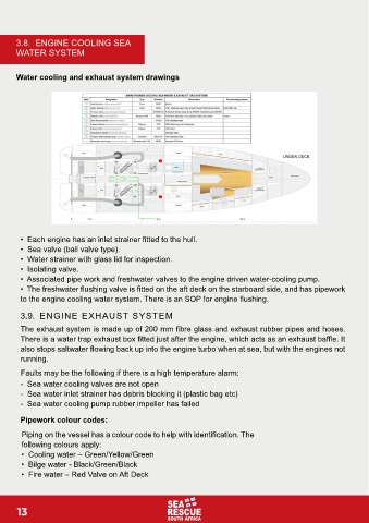
Water cooling and exhaust system drawings
• Each engine has an inlet strainer fitted to the hull.
• Sea valve (ball valve type).
• Water strainer with glass lid for inspection.
• Isolating valve.
• Associated pipe work and freshwater valves to the engine driven water-cooling pump.
• The freshwater flushing valve is fitted on the aft deck on the starboard side, and has pipework
to the engine cooling water system. There is an SOP for engine flushing.
3.9. ENGINE EXHAUST SYSTEM
The exhaust system is made up of 200 mm fibre glass and exhaust rubber pipes and hoses.
There is a water trap exhaust box fitted just after the engine, which acts as an exhaust baffle. It
also stops saltwater flowing back up into the engine turbo when at sea, but with the engines not
running.
Faults may be the following if there is a high temperature alarm:
- Sea water cooling valves are not open
- Sea water inlet strainer has debris blocking it (plastic bag etc)
- Sea water cooling pump rubber impeller has failed
Pipework colour codes:
Piping on the vessel has a colour code to help with identification. The
following colours apply:
• Cooling water – Green/Yellow/Green
• Bilge water - Black/Green/Black
• Fire water – Red Valve on Aft Deck
13