
Page 328 - Programmable Logic Controllers, Fifth Edition - Mobile version
P. 328
monitor, diagnose, and manage the application. Depend-
ing on the requirements and complexity of the process, Error Disturbance
the operator may be required to: amplifier
Set-point + Controller Output Process
• Stop and start the process. – Error actuator
signal
• Operate the controls and make the adjustments
required for the process and monitor its progress. Input
• Detect abnormal situations and undertake corrective Process variable signal sensors Feedback
action. path
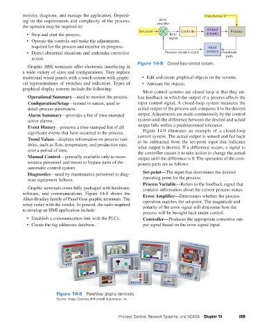
Figure 14-9 Closed-loop control system.
Graphic HMI terminals offer electronic interfacing in
a wide variety of sizes and configurations. They replace
traditional wired panels with a touch screen with graphi- • Edit and create graphical objects on the screens.
cal representations of switches and indicators. Types of • Animate the objects.
graphical display screens include the following:
Most control systems are closed loop in that they uti-
Operational Summary—used to monitor the process. lize feedback in which the output of a process affects the
Configuration/Setup—textual in nature, used to input control signal. A closed-loop system measures the
detail process parameters. actual output of the process and compares it to the desired
Alarm Summary—provides a list of time-stamped output. Adjustments are made continuously by the control
active alarms. system until the difference between the desired and actual
Event History—presents a time-stamped list of all output falls within a predetermined tolerance.
significant events that have occurred in the process. Figure 14-9 illustrates an example of a closed-loop
Trend Values—displays information on process vari- control system. The actual output is sensed and fed back
to be subtracted from the set-point input that indicates
ables, such as flow, temperature, and production rate, what output is desired. If a difference occurs, a signal to
over a period of time. the controller causes it to take action to change the actual
Manual Control—generally available only to main- output until the difference is 0. The operation of the com-
tenance personnel and meant to bypass parts of the ponent parts are as follows:
automatic control system.
Diagnostics—used by maintenance personnel to diag- Set-point—The input that determines the desired
nose equipment failures. operating point for the process.
Process Variable—Refers to the feedback signal that
Graphic terminals come fully packaged with hardware, contains information about the current process status.
software, and communications. Figure 14-8 shows the Error Amplifier—Determines whether the process
Allen-Bradley family of PanelView graphic terminals. The operation matches the set-point. The magnitude and
setup varies with the vendor. In general, the tasks required polarity of the error signal will determine how the
to develop an HMI application include:
process will be brought back under control.
• Establish a communication link with the PLCs. Controller—Produces the appropriate corrective out-
• Create the tag addresses database. put signal based on the error signal input.
Figure 14-8 PanelView graphic terminals.
Source: Image Courtesy of Rockwell Automation, Inc.
Process Control, Network Systems, and SCADA Chapter 14 309
pet73842_ch14_305-332.indd 309 05/11/15 4:27 PM