
Page 333 - Programmable Logic Controllers, Fifth Edition - Mobile version
P. 333
Either programmable controllers can be fitted with
input/output modules that produce PID control, or they • Integral gain also provides power, even if the error
is zero (e.g., even when an oven reaches its set-
will already have sufficient mathematical functions to point, it still needs power to stay hot).
allow PID control to be carried out. PID is essentially • Without this base power, the controller will droop
an equation that the controller uses to evaluate the con- and hunt for the set-point.
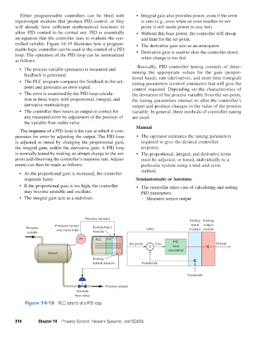
trolled variable. Figure 14-19 illustrates how a program- • The derivative gain acts as an anticipator.
mable logic controller can be used in the control of a PID • Derivative gain is used to slow the controller down
loop. The operation of the PID loop can be summarized when change is too fast.
as follows:
Basically, PID controller tuning consists of deter-
• The process variable (pressure) is measured and mining the appropriate values for the gain (propor-
feedback is generated. tional band), rate (derivative), and reset time (integral)
• The PLC program compares the feedback to the set- tuning parameters (control constants) that will give the
point and generates an error signal. control required. Depending on the characteristics of
• The error is examined by the PID loop calcula- the deviation of the process variable from the set-point,
tion in three ways: with proportional, integral, and the tuning parameters interact to alter the controller’s
derivative methodology. output and produce changes in the value of the process
• The controller then issues an output to correct for variable. In general, three methods of controller tuning
any measured error by adjustment of the position of are used:
the variable flow outlet valve.
Manual
The response of a PID loop is the rate at which it com-
pensates for error by adjusting the output. The PID loop • The operator estimates the tuning parameters
is adjusted or tuned by changing the proportional gain, required to give the desired controller
the integral gain, and/or the derivative gain. A PID loop response.
is normally tested by making an abrupt change to the set- • The proportional, integral, and derivative terms
point and observing the controller’s response rate. Adjust- must be adjusted, or tuned, individually to a
ments can then be made as follows: particular system using a trial-and-error
method.
• As the proportional gain is increased, the controller
responds faster. Semiautomatic or Autotune
• If the proportional gain is too high, the controller • The controller takes care of calculating and setting
may become unstable and oscillate. PID parameters.
• The integral gain acts as a stabilizer. – Measures sensor output
Process variable
Analog Analog
Pressure sensor input output
Process and transmitter Analog input CPU module module
supply module
PT PLC CPU
Set-point Error PID Output
S loop
calculation
Vessel
Analog
output module Feedback
Feedback
Process output
Variable
flow valve
Figure 14-19 PLC control of a PID loop.
314 Chapter 14 Process Control, Network Systems, and SCADA
pet73842_ch14_305-332.indd 314 05/11/15 4:27 PM