
Page 331 - Programmable Logic Controllers, Fifth Edition - Mobile version
P. 331
Variable (PV), while the desired temperature is
100% - 200 W • The current temperature is called the Process
known as the Set-Point (SP).
• The proportional controller changes the controller
50% - 100 W
output in proportion to the difference between the
SP and PV. The greater the difference, the greater
the corrective action applied.
25% - 50 W
• At the set-point (the midpoint of the proportional
band), the output on:off ratio is 1:1; that is, the on
200 W
230 V 12.5% - 25 W time and off time are equal.
• If the temperature is further from the set-point, the
on and off times vary in proportion to the tempera-
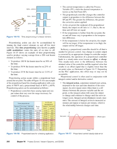
Figure 14-15 Time proportioning of a heater element.
ture difference.
• If the temperature is below the set-point, the output
Proportioning action can also be accomplished by will be on longer; if the temperature is too high, the
turning the final control element on and off for short output will be off longer.
intervals. This time proportioning (also known as pulse
width modulation) varies the ratio of on time to off. In theory, a proportional controller should be all that is
Figure 14-15 shows an example of time proportioning needed for process control. Any change in system output
used to produce varying wattage from a 200 watt heater is corrected by an appropriate change in controller output.
element as follows: Unfortunately, the operation of a proportional controller
leads to a steady-state error known as offset, or droop.
• To produce 100 W the heater must be on 50% of This steady-state error is the difference between the
the time. attained value of the controller and the required value that
• To produce 50 W the heater must be on 25% of results in an offset signal that is slightly lower than the
the time. set-point value, as illustrated in Figure 14-17. Depending
• To produce 25 W the heater must be on 12.5% of on the PLC application, this offset may or may not be
the time. acceptable.
Proportional control is often used in conjunction with
Proportioning action occurs within a proportional band integral control and/or derivative control.
around the set-point. The table of Figure 14-16 is an example
of the proportional band for a heating application with a set- • The integral action, sometimes termed reset action,
point of 500°F and a proportional band of 80°F (±40°F). responds to the size and time duration of the error
Proportioning action can be summarized as follows: signal. An error signal exists when there is a dif-
• Proportional controllers have analog input and out- ference between the process variable and the set-
put values that vary over the range necessary for point, so the integral action will cause the output
control of the process. to change and continue to change until the error no
longer exists. Integral action eliminates steady-state
error. The amount of integral action is measured as
4–20 mA minutes per repeat or repeats per minute, which is
Time proportional
proportional the relationship between changes and time.
Percent On time O time Temp. Output Percent
on (seconds) (seconds) (°F) level output
0.0 0.0 20.0 over 540 4 mA 0.0
0.0 0.0 20.0 540.0 4 mA 0.0
12.5 2.5 17.5 530.0 6 mA 12.5
25.0 5.0 15.0 520.0 8 mA 25.0 Set-point O set signal
37.5 7.5 12.5 510.0 10 mA 37.5
5 0 0 50.0 10.0 10.0 500.0 12 mA 50.0
62.5 12.5 7.5 490.0 14 mA 62.5
75.0 15.0 5.0 480.0 16 mA 75.0
87.5 17.5 2.5 470.0 18 mA 87.5
100.0 20.0 0.0 460.0 20 mA 100.0
100.0 20.0 0.0 under 460 20 mA 100.0 Time
Figure 14-16 Proportional band for a heating application. Figure 14-17 Proportional control steady-state error.
312 Chapter 14 Process Control, Network Systems, and SCADA
pet73842_ch14_305-332.indd 312 05/11/15 4:27 PM