


Page 1044 - Basic Electrical Engineering
P. 1044
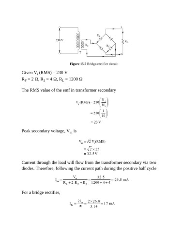
Figure 15.7 Bridge-rectifier circuit


               Given V  (RMS) = 230 V
                          i
               R  = 2 Ω, R  = 4 Ω, R  = 1200 Ω
                              2
                 F
                                          L
               The RMS value of the emf in transformer secondary


               Peak secondary voltage, V  is
                                               m


               Current through the load will flow from the transformer secondary via two
               diodes. Therefore, following the current path during the positive half cycle


               For a bridge rectifier,

