


Page 1048 - Basic Electrical Engineering
P. 1048
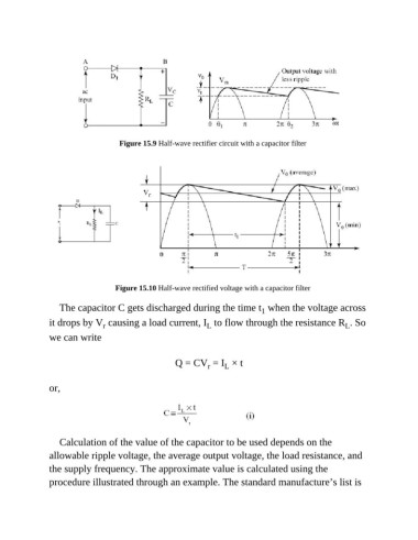
Figure 15.9 Half-wave rectifier circuit with a capacitor filter


                                   Figure 15.10 Half-wave rectified voltage with a capacitor filter


                  The capacitor C gets discharged during the time t  when the voltage across
                                                                              1
               it drops by V  causing a load current, I  to flow through the resistance R . So
                               r
                                                                                                      L
                                                              L
               we can write

                                                    Q = CV  = I  × t
                                                                   L
                                                              r
               or,


                  Calculation of the value of the capacitor to be used depends on the

               allowable ripple voltage, the average output voltage, the load resistance, and
               the supply frequency. The approximate value is calculated using the

               procedure illustrated through an example. The standard manufacture’s list is

