


Page 1053 - Basic Electrical Engineering
P. 1053
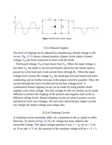
Figure 15.14 Positive shunt clipper


                                                 15.3.3 Biased Clippers

               The level of clipping can be adjusted by introducing a biased voltage in the

               circuit. Fig. 15.15 shows a biased positive clipper circuit where a biased
               voltage, V  has been connected in series with the diode.
                            B
                  The biased voltage, V  is kept lower than V . When the input voltage is
                                             B
                                                                       m
               less than V , the diode is not forward biased, and hence the whole input is
                             B
               passed on to the load and a load current flows through R . When the input
                                                                                   L
               voltage level crosses the voltage V , the diode gets forward biased and starts
                                                         B
               conducting, and no further increase in the output current is possible. Thus, the
               current through the load is resistricted by the bias voltage level. A

               combination biased clipping circuit can be made by using another diode
               together with a bias voltage. The bias voltage for the two diodes can be made

               different to achieve the clipping of the positive and negative half cycles at
               different voltage levels. Biased clipping circuits are used to protect circuits
               and devices from over voltages. We have also observed that clipper circuits

               can change the output voltage wave shape also.


                                               15.3.4 Clamping Circuits


               A clamping circuit essentially adds a dc component to the ac signal in either
               direction. As shown in Fig. 15.16 a dc voltage has been added to the
               sinusoidal voltage. The signal voltage equation is say, ν = v  sin ωt = 5 sin
                                                                                       m
               ωt. If we add +5 V dc, the equation of the resultant voltage will be ν = 5 + 5

