


Page 1054 - Basic Electrical Engineering
P. 1054
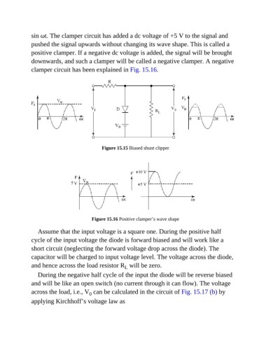
sin ωt. The clamper circuit has added a dc voltage of +5 V to the signal and
               pushed the signal upwards without changing its wave shape. This is called a
               positive clamper. If a negative dc voltage is added, the signal will be brought

               downwards, and such a clamper will be called a negative clamper. A negative
               clamper circuit has been explained in Fig. 15.16.


                                                Figure 15.15 Biased shunt clipper


                                           Figure 15.16 Positive clamper’s wave shape


                  Assume that the input voltage is a square one. During the positive half
               cycle of the input voltage the diode is forward biased and will work like a

               short circuit (neglecting the forward voltage drop across the diode). The
               capacitor will be charged to input voltage level. The voltage across the diode,

               and hence across the load resistor R  will be zero.
                                                          L
                  During the negative half cycle of the input the diode will be reverse biased

               and will be like an open switch (no current through it can flow). The voltage
               across the load, i.e., V  can be calculated in the circuit of Fig. 15.17 (b) by
                                          0
               applying Kirchhoff’s voltage law as

