


Page 1052 - Basic Electrical Engineering
P. 1052
Like series clippers, shunt clippers can also clip off the positive half cycle or
               the negative half cycle of the input.
                  Figure 15.14 shows a positive shunt clipper circuit where the diode is

               connected in parallel, i.e., in shunt with the load resistance R .
                                                                                        L
                  When the input voltage is positive the diode is forward biased and is in
               conducting mode. The voltage drop across the diode V , which is only 0.7 V
                                                                                 F
               for a silicon diode will appear across the load. Thus, effectively the positive
               half cycle of the input voltage is clipped off and the output voltage will be

               nearly zero. When the input voltage is negative the diode is reverse biased.
               Current flows through the load resistance R  and the series resistance R. The
                                                                    L
               voltage drop across R is I  R which is small as compared to the voltage drop
                                              L
               across the load resistance R . The output voltage V  is nearly equal to the
                                                 L
                                                                             0
               negative input voltage as has been shown. Resistance R is connected in the
               circuit to limit the diode current when it is forward biased.
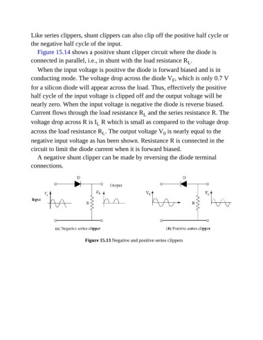
                  A negative shunt clipper can be made by reversing the diode terminal

               connections.


                                         Figure 15.13 Negative and positive series clippers

