


Page 1050 - Basic Electrical Engineering
P. 1050
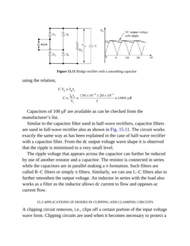
Figure 15.11 Bridge rectifier with a smoothing capacitor


               using the relation,


                  Capacitors of 100 μF are available as can be checked from the
               manufacturer’s list.

                  Similar to the capacitor filter used in half-wave rectifiers, capacitor filters
               are used in full-wave rectifier also as shown in Fig. 15.11. The circuit works

               exactly the same way as has been explained in the case of half-wave rectifier
               with a capacitor filter. From the dc output voltage wave shape it is observed

               that the ripple is minimized to a very small level.
                  The ripple voltage that appears across the capacitor can further be reduced

               by use of another resistor and a capacitor. The resistor is connected in series
               while the capacitors are in parallel making a π formation. Such filters are
               called R–C filters or simply π filters. Similarly, we can use L–C filters also to

               further smoothen the output voltage. An inductor in series with the load also
               works as a filter as the inductor allows dc current to flow and opposes ac

               current flow.


                         15.3 APPLICATIONS OF DIODES IN CLIPPING AND CLAMPING CIRCUITS

               A clipping circuit removes, i.e., clips off a certain portion of the input voltage
               wave form. Clipping circuits are used when it becomes necessary to protect a

