


Page 1051 - Basic Electrical Engineering
P. 1051
circuit or a device that might get destroyed due to large amplitude signal. In
               fact, the half-wave rectifier described earlier is a clipper circuit. It clips off
               the negative half cycle and allows only the positive half cycle. A clipping

               circuit, or also called a clipper is used to clip off certain unwanted portions of
               the wave form which may lead to noise, and deteriote the performance of the

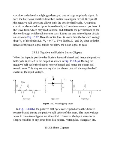
               device through which such currents pass. Let us see one noise clipper circuit
               as shown in Fig. 15.12. Here the noise level is lower than the forward voltage

               drop V  of the diodes i.e., V  = 0.7 V. Two diodes, D  and D  clear both the
                                                                                1
                                                                                         2
                        F
                                                 F
               halves of the main signal but do not allow the noise signal to pass.

                                   15.3.1 Negative and Positive Series Clippers

               When the input is positive the diode is forward biased, and hence the positive
               half cycle is passed to the output as shown in Fig. 15.13 (a). During the

               negative half cycle the diode is reverse biased, and hence the output will
               remain zero. This way we can say that the circuit cuts off the negative half

               cycles of the input voltage.


                                               Figure 15.12 Noise clipping circuit


                  In Fig. 15.13 (b), the positive half cycles are clipped off as the diode is
               reverse biased during the positive half cycles of the input. The input voltage

               wave in these two clippers are sinusoidal. However, the input wave form
               shapes could be of any other form like square, rectangular, triangular, etc.


                                                 15.3.2 Shunt Clippers

