


Page 1046 - Basic Electrical Engineering
P. 1046
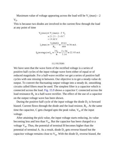
Maximum value of voltage appearing across the load will be V  (max) – 2
                                                                                              i
               V .
                  F
               This is because two diodes are involved in the current flow through the load

               at any point of time


                                                        15.2 FILTERS

               We have seen that the wave form of the rectified voltage is a series of

               positive half cycles of the input voltage wave form either of equal or of
               reduced magnitude. For a half-wave rectifier we get a series of positive half

               cycles with one missing in between. Our objective is to get a steady-value dc
               output. To convert the fluctuating output voltage into a steady dc, smoothing
               circuits called filters must be used. The simplest filter is a capacitor which is

               connected across the load. Fig. 15.9 shows a capacitor C connected across the
               load resistance R  in a half-wave rectifier. The effect of the use of a capacitor
                                    L
               on the output voltage wave has been shown.
                  During the positive half cycle of the input voltage the diode D  is forward
                                                                                             1
               biased. Current flows through the diode and the load resistor, R . At the same
                                                                                            L
               time the capacitor, C gets charged upto the peak value, V  of the input
                                                                                    m
               voltage.

                  After attaining the pick value, the input voltage starts reducing, its value
               becoming less and less than V . But the capacitor has been charged to a
                                                    m
               voltage V . Thus, the potential of terminal B becomes higher than the
                           m
               potential of terminal A. As a result, diode D  gets reverse biased but the
                                                                    1
               capacitor voltage remains close to V . With the diode D  reverse biased, the
                                                           m
                                                                                   1

