


Page 1047 - Basic Electrical Engineering
P. 1047
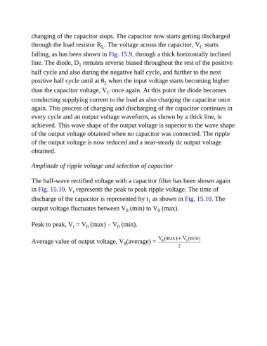
changing of the capacitor stops. The capacitor now starts getting discharged
               through the load resistor R . The voltage across the capacitor, V  starts
                                                                                             C
                                               L
               falling, as has been shown in Fig. 15.9, through a thick horizontally inclined
               line. The diode, D  remains reverse biased throughout the rest of the positive
                                     1
               half cycle and also during the negative half cycle, and further to the next
               positive half cycle until at θ  when the input voltage starts becoming higher
                                                 2
               than the capacitor voltage, V  once again. At this point the diode becomes
                                                  C
               conducting supplying current to the load as also charging the capacitor once
               again. This process of charging and discharging of the capacitor continues in

               every cycle and an output voltage waveform, as shown by a thick line, is
               achieved. This wave shape of the output voltage is superior to the wave shape

               of the output voltage obtained when no capacitor was connected. The ripple
               of the output voltage is now reduced and a near-steady dc output voltage
               obtained.


               Amplitude of ripple voltage and selection of capacitor


               The half-wave rectified voltage with a capacitor filter has been shown again

               in Fig. 15.10. V  represents the peak to peak ripple voltage. The time of
                                  r
               discharge of the capacitor is represented by t  as shown in Fig. 15.10. The
                                                                     1
               output voltage fluctuates between V  (min) to V  (max).
                                                           0
                                                                         0

               Peak to peak, V  = V  (max) – V  (min).
                                  r
                                        0
                                                       0
               Average value of output voltage, V (average) =
                                                          0

