


Page 1134 - Basic Electrical Engineering
P. 1134
17.7.6 An IC 555 Timer Astable Oscillator Circuit

               A practical circuit of an IC 555 timer astable oscillator circuit has been
               shown in Fig. 17.13 drawn in a slightly different way. The students may try

               out this circuit for its working. We may choose R = R  = 10 kΩ, C = 10 µF,
                                                                                1
               C  = 0.01µF, supply voltage to the IC, i.e., V  = +9 V, a red LED, a series
                 1
                                                                      CC
               resistance of 470 Ω. The LED red light has been used to indicate clearly that

               the circuit is working. A LED will require about 5 mA to 20 mA of current to
               emit light.

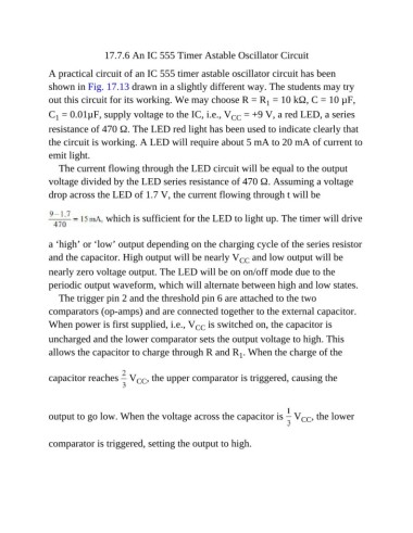
                  The current flowing through the LED circuit will be equal to the output
               voltage divided by the LED series resistance of 470 Ω. Assuming a voltage

               drop across the LED of 1.7 V, the current flowing through t will be


                                 which is sufficient for the LED to light up. The timer will drive


               a ‘high’ or ‘low’ output depending on the charging cycle of the series resistor
               and the capacitor. High output will be nearly V  and low output will be
                                                                        CC
               nearly zero voltage output. The LED will be on on/off mode due to the
               periodic output waveform, which will alternate between high and low states.

                  The trigger pin 2 and the threshold pin 6 are attached to the two
               comparators (op-amps) and are connected together to the external capacitor.

               When power is first supplied, i.e., V  is switched on, the capacitor is
                                                           CC
               uncharged and the lower comparator sets the output voltage to high. This

               allows the capacitor to charge through R and R . When the charge of the
                                                                        1


               capacitor reaches   V , the upper comparator is triggered, causing the
                                         CC


               output to go low. When the voltage across the capacitor is   V , the lower
                                                                                          CC


               comparator is triggered, setting the output to high.

