


Page 1131 - Basic Electrical Engineering
P. 1131
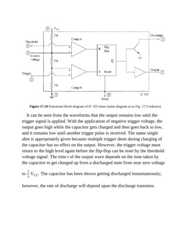
Figure 17.10 Functional block diagram of IC 555 timer (same diagram as in Fig. 17.9 redrawn)


                  It can be seen from the waveforms that the output remains low until the
               trigger signal is applied. With the application of negative trigger voltage, the

               output goes high while the capacitor gets charged and then goes back to low,
               and it remains low until another trigger pulse is received. The name single
               shot is appropriately given because multiple trigger shots during charging of

               the capacitor has no effect on the output. However, the trigger voltage must
               return to the high level again before the flip-flop can be reset by the threshold

               voltage signal. The time t of the output wave depends on the time taken by
               the capacitor to get charged up from a discharged state from near zero voltage


               to   V . The capacitor has been shown getting discharged instantaneously;
                       CC


               however, the rate of discharge will depend upon the discharge transistor.

