


Page 1126 - Basic Electrical Engineering
P. 1126
Monostable multivibrator generates a single cycle, and hence can be used
               to provide gate pulse to other circuits. Astable circuit is used to generate
               square waves. Both these circuits are used extensively in pulse circuitry.


                                         17.7.2 Pin Configuration of IC 555

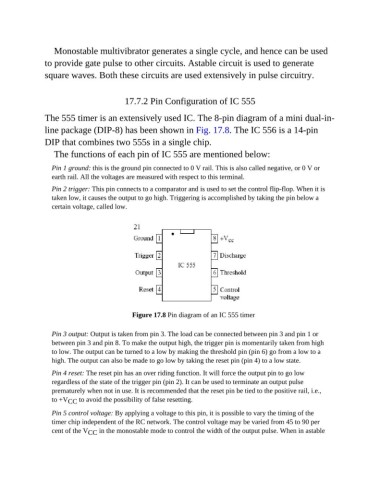
               The 555 timer is an extensively used IC. The 8-pin diagram of a mini dual-in-

               line package (DIP-8) has been shown in Fig. 17.8. The IC 556 is a 14-pin
               DIP that combines two 555s in a single chip.
                  The functions of each pin of IC 555 are mentioned below:

                  Pin 1 ground: this is the ground pin connected to 0 V rail. This is also called negative, or 0 V or
                  earth rail. All the voltages are measured with respect to this terminal.

                  Pin 2 trigger: This pin connects to a comparator and is used to set the control flip-flop. When it is
                  taken low, it causes the output to go high. Triggering is accomplished by taking the pin below a
                  certain voltage, called low.


                                            Figure 17.8 Pin diagram of an IC 555 timer


                  Pin 3 output: Output is taken from pin 3. The load can be connected between pin 3 and pin 1 or
                  between pin 3 and pin 8. To make the output high, the trigger pin is momentarily taken from high
                  to low. The output can be turned to a low by making the threshold pin (pin 6) go from a low to a
                  high. The output can also be made to go low by taking the reset pin (pin 4) to a low state.

                  Pin 4 reset: The reset pin has an over riding function. It will force the output pin to go low
                  regardless of the state of the trigger pin (pin 2). It can be used to terminate an output pulse
                  prematurely when not in use. It is recommended that the reset pin be tied to the positive rail, i.e.,
                  to +V CC  to avoid the possibility of false resetting.

                  Pin 5 control voltage: By applying a voltage to this pin, it is possible to vary the timing of the
                  timer chip independent of the RC network. The control voltage may be varied from 45 to 90 per
                  cent of the V CC  in the monostable mode to control the width of the output pulse. When in astable

