


Page 1129 - Basic Electrical Engineering
P. 1129
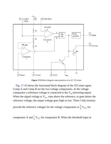
Figure 17.9 Block diagram representation of an IC 555 timer

                  Fig. 17.10 shows the functional block diagram of the 555 timer again.
               Comp A and Comp B are the two voltage comparators. In the voltage

               comparator a reference voltage is connected to the V -(inverting input).
                                                                               in
               When the signal voltage at V       in+  rises above the reference, or goes below the
               reference voltage, the output voltage goes high or low. Three 5 kΩ resistors


               provide the reference voltages for the voltage comparators at   V  for
                                                                                              CC


               comparator A and   V       CC  for comparator B. When the threshold input at

