


Page 1132 - Basic Electrical Engineering
P. 1132
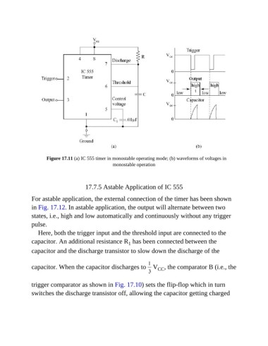
Figure 17.11 (a) IC 555 timer in monostable operating mode; (b) waveforms of voltages in
                                                    monostable operation


                                        17.7.5 Astable Application of IC 555

               For astable application, the external connection of the timer has been shown

               in Fig. 17.12. In astable application, the output will alternate between two
               states, i.e., high and low automatically and continuously without any trigger

               pulse.
                  Here, both the trigger input and the threshold input are connected to the
               capacitor. An additional resistance R  has been connected between the
                                                            1
               capacitor and the discharge transistor to slow down the discharge of the


               capacitor. When the capacitor discharges to   V , the comparator B (i.e., the
                                                                         CC


               trigger comparator as shown in Fig. 17.10) sets the flip-flop which in turn
               switches the discharge transistor off, allowing the capacitor getting charged

