


Page 1128 - Basic Electrical Engineering
P. 1128
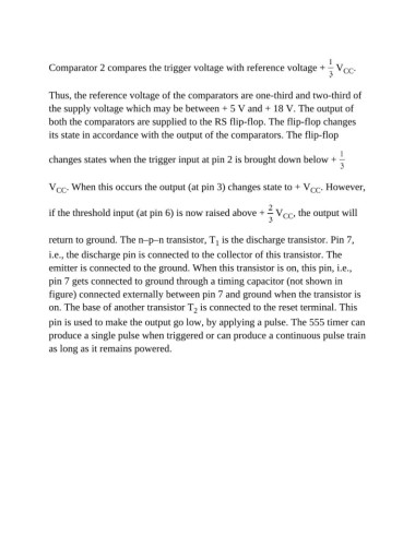
Comparator 2 compares the trigger voltage with reference voltage +   V .
                                                                                                      CC


               Thus, the reference voltage of the comparators are one-third and two-third of
               the supply voltage which may be between + 5 V and + 18 V. The output of

               both the comparators are supplied to the RS flip-flop. The flip-flop changes
               its state in accordance with the output of the comparators. The flip-flop


               changes states when the trigger input at pin 2 is brought down below +


               V  CC . When this occurs the output (at pin 3) changes state to + V . However,
                                                                                             CC


               if the threshold input (at pin 6) is now raised above +   V          CC , the output will


               return to ground. The n–p–n transistor, T  is the discharge transistor. Pin 7,
                                                                 1
               i.e., the discharge pin is connected to the collector of this transistor. The

               emitter is connected to the ground. When this transistor is on, this pin, i.e.,
               pin 7 gets connected to ground through a timing capacitor (not shown in

               figure) connected externally between pin 7 and ground when the transistor is
               on. The base of another transistor T  is connected to the reset terminal. This
                                                          2
               pin is used to make the output go low, by applying a pulse. The 555 timer can
               produce a single pulse when triggered or can produce a continuous pulse train

               as long as it remains powered.

