


Page 1133 - Basic Electrical Engineering
P. 1133
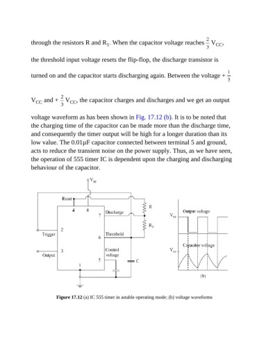
through the resistors R and R . When the capacitor voltage reaches   V                CC ,
                                                  1


               the threshold input voltage resets the flip-flop, the discharge transistor is


               turned on and the capacitor starts discharging again. Between the voltage +


               V  CC  and +   V  CC , the capacitor charges and discharges and we get an output


               voltage waveform as has been shown in Fig. 17.12 (b). It is to be noted that

               the charging time of the capacitor can be made more than the discharge time,
               and consequently the timer output will be high for a longer duration than its

               low value. The 0.01µF capacitor connected between terminal 5 and ground,
               acts to reduce the transient noise on the power supply. Thus, as we have seen,

               the operation of 555 timer IC is dependent upon the charging and discharging
               behaviour of the capacitor.


                           Figure 17.12 (a) IC 555 timer in astable operating mode; (b) voltage waveforms

