Page 259 - Basic Electrical Engineering
P. 259

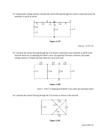
52. Using modal voltage analysis calculate the current flowing through the resistor connected across the
                  terminals A and B as shown.


                                                         Figure 2.179

                                                                                          [Ans I  = 0.371 A]
                                                                                               1


               53. Calculate the current flowing through the 2 Ω resistor connected across terminals A and B in the
                  network shown by (i) applying Kirchhoff’s laws; (ii) applying Thevenin’s theorem; (iii) nodal
                  voltage analysis. Compare the time taken by you in each case.


                                                         Figure 2.180

                                           [Ans I = 0.817 A Applying Kirchhoff’s laws takes the maximum time]


               54. Calculate the current flowing through the 5 Ω resistor as shown in the network.


                                                         Figure 2.181

                                                                                              [Ans 0.663 A]
   254   255   256   257   258   259   260   261   262   263   264