
Page 319 - Basic Electrical Engineering
P. 319
OB. The voltage drop across the capacitance V lags the current by 90° and
C
is represented by BC. The phasor OC is the phasor sum of two voltages V R
and V . Hence, the OC represents the applied voltages. Thus, in a capacitive
C
circuit, current leads the voltages by an angle ϕ. The same phasor diagram
can be drawn by taking voltage, V as the reference vector as shown in Fig.
3.23 (b).
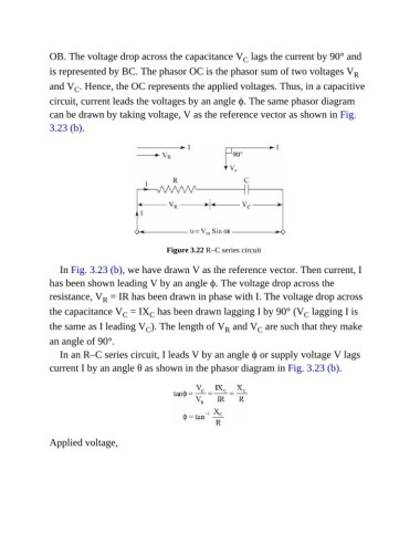
Figure 3.22 R–C series circuit
In Fig. 3.23 (b), we have drawn V as the reference vector. Then current, I
has been shown leading V by an angle ϕ. The voltage drop across the
resistance, V = IR has been drawn in phase with I. The voltage drop across
R
the capacitance V = IX has been drawn lagging I by 90° (V lagging I is
C
C
C
the same as I leading V ). The length of V and V are such that they make
R
C
C
an angle of 90°.
In an R–C series circuit, I leads V by an angle ϕ or supply voltage V lags
current I by an angle θ as shown in the phasor diagram in Fig. 3.23 (b).
Applied voltage,