
Page 323 - Basic Electrical Engineering
P. 323
The circuit will effectively be inductive in nature. When X > X , obviously,
C
L
IX , i.e., V is greater than IX , i.e., V . So the resultant of V and V will
L
C
L
C
C
L
be V – V so that V is the phasor sum of V and (V – V ). The phasor sum
C
C
L
R
L
of V and (V – V ) gives the resultant supply voltage V. This is shown in
C
R
L
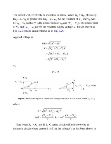
Fig. 3.25 (b) and again redrawn as in Fig. 3.26.
Applied voltage is
or,
V = IZ
Figure 3.26 Phasor diagram of current and voltage drops in an R–L–C circuit where X > X C
L
where
Note when X > X , the R–L–C series circuit will effectively be an
L
C
inductive circuit where current I will lag the voltage V as has been shown in