
Page 324 - Basic Electrical Engineering
P. 324
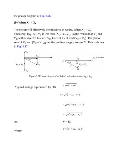
the phasor diagram of Fig. 3.26.


               (b) When X  < X       C
                              L

               The circuit will effectively be capacitive in nature. When X  < X ,
                                                                                              C
                                                                                       L
               obviously, IX , i.e., V  is less than IX , i.e., V . So the resultant of V  and
                                                             C
                                                                        C
                                L
                                          L
                                                                                                   L
               V  will be directed towards V . Current I will lead (V  – V ). The phasor
                                                                                       L
                                                    C
                                                                                 C
                  C
               sum of V  and (V  – V  gives the resultant supply voltage V. This is shown
                                            L)
                           R
                                     C
               in Fig. 3.27.


                               Figure 3.27 Phasor diagram of an R–L–C series circuit when X  < X C
                                                                                         L


                Applied voltage represented by OB


                or,                                              V = IZ


                where