
Page 322 - Basic Electrical Engineering
P. 322
where cos ϕ=Power factor of the circuit.
Note: Power factor, cosf is lagging for an inductive circuit and is leading
for a capacitive circuit.
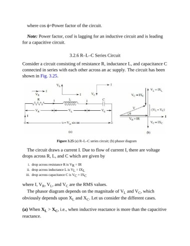
3.2.6 R–L–C Series Circuit
Consider a circuit consisting of resistance R, inductance L, and capacitance C
connected in series with each other across an ac supply. The circuit has been
shown in Fig. 3.25.
Figure 3.25 (a) R–L–C series circuit; (b) phasor diagram
The circuit draws a current I. Due to flow of current I, there are voltage
drops across R, L, and C which are given by
i. drop across resistance R is V = IR
R
ii. drop across inductance L is V = IX L
L
iii. drop across capacitance C is V = IX C
C
where I, V , V , and V are the RMS values.
L
R
C
The phasor diagram depends on the magnitude of V and V , which
C
L
obviously depends upon X and X . Let us consider the different cases.
C
L
(a) When X > X , i.e., when inductive reactance is more than the capacitive
L
C
reactance.