
Page 359 - Basic Electrical Engineering
P. 359
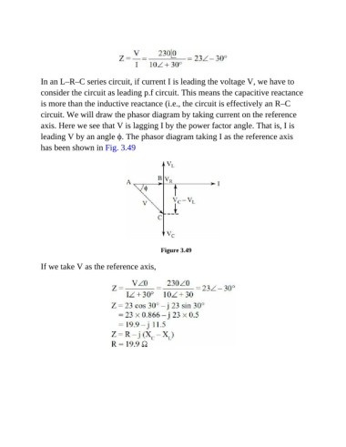
In an L–R–C series circuit, if current I is leading the voltage V, we have to

               consider the circuit as leading p.f circuit. This means the capacitive reactance
               is more than the inductive reactance (i.e., the circuit is effectively an R–C

               circuit. We will draw the phasor diagram by taking current on the reference
               axis. Here we see that V is lagging I by the power factor angle. That is, I is

               leading V by an angle ϕ. The phasor diagram taking I as the reference axis
               has been shown in Fig. 3.49


                                                          Figure 3.49

               If we take V as the reference axis,